National Instruments CFP-RLY-421 User Manual Page 7
- Page / 14
- Table of contents
- BOOKMARKS
- FP-RLY-421 1
- Installing the cFP-RLY-421 2
- Wiring the cFP-RLY-421 3
- Figure 2. Connecting a Load 5
- Protection Circuits 6
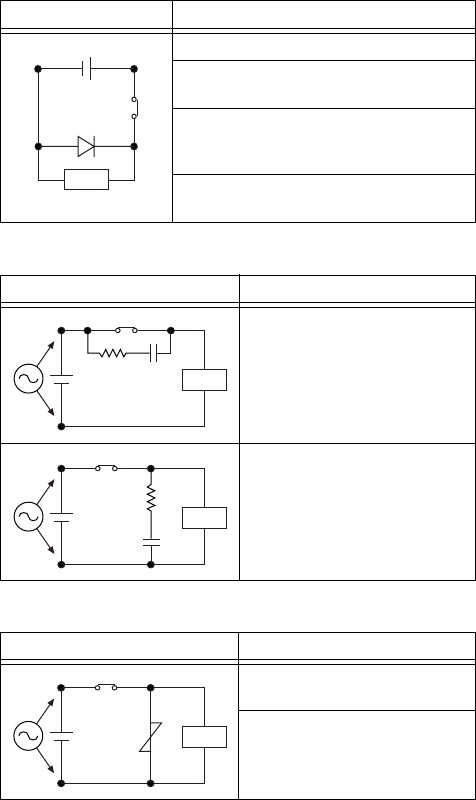
- Diode Circuit 7
- CR Circuits 7
- Varistor Circuit 7
- Status Indicators 8
- Specifications 11
- Physical 12
- Power Requirements 12
- Isolation Voltage 12
- Environmental 12
- Shock and Vibration 12
- Electromagnetic Compatibility 13
- CE Compliance 13
- Where to Go for Support 14
Related products and manuals for Voltage regulators National Instruments CFP-RLY-421
 (7 pages)
© 2020, manymanuals.com. All rights reserved. | 0.259 s |
 Manymanuals.com
 Manymanuals.de
 Manymanuals.fr
 Manymanuals.it
 Manymanuals.pl
 Manymanuals.cz
 Manymanuals.es
 Manymanuals-pt.com
Comments to this Manuals